EN
 AR
 HR
 CS
 NL
 FR
 DE
 EL
 HI
 IT
 JA
 KO
 NO
 PL
 PT
 RO
 RU
 ES
 SV
 TL
 IW
 ID
 SR
 SK
 UK
 VI
 ET
 HU
 TH
 TR
 FA
 MS
 GA
 HY
 AZ
 UR
 BN
 LA
 MN
 KK

Field Service Case Study: Tanbos Supports 9 Renewable Energy Sites with Specialized Cable Fault Diagnosis
Overview
In 2026, Tanbos, a proprietary brand of Xianheng International, provided cable and overhead line fault diagnosis services to nine renewable energy sites across China. The projects covered solar photovoltaic (PV), wind power and hydropower applications, addressing six major categories of cable testing, fault location and insulation assessment challenges.
The assignments involved a wide range of operating conditions, from buried medium-voltage collection cables and low-voltage power cables to DC cables in solar PV systems. The team also carried out cable route tracing, localized fault location and partial discharge testing to help customers assess cable conditions, plan maintenance and reduce risks during construction and operation.
These field applications demonstrate how appropriate diagnostic equipment, systematic testing procedures and practical engineering experience can support the safe and reliable operation of renewable energy infrastructure.
1. Nine Sites, Diverse Cable Testing Requirements
Renewable energy facilities rely on extensive cable networks to transfer electricity from generating units to collection systems and substations. While PV modules, wind turbines and transmission structures are visible, many potential risks lie in buried cables, cable trenches, cable trays and connections between underground and overhead sections.
Incomplete cable route records, insulation deterioration and faults in inaccessible locations can complicate maintenance and construction planning.
In 2026, the Tanbos team delivered field services across Shanxi, Xinjiang, Jiangsu and Fujian, covering nine renewable energy sites and a broad range of cable diagnostic requirements.
| Month | Application | Main Testing Task |
| March | Solar PV / wind farm, Shanxi | Live cable route tracing for a 35 kV three-core cable |
| March | Solar PV plant, Shanxi | Low-resistance main insulation fault on a 1 kV cable |
| April | Solar PV plant, Xinjiang | Ground fault on a 750 V DC PV string cable |
| April | Hydropower plant, Xinjiang | Single-phase ground fault on a 400 V pump motor feeder |
| June | Solar PV site, Fujian | Partial discharge testing and routine inspection |
| June | Wind farm, Jiangsu | VLF oscillating wave partial discharge testing on a 35 kV three-core cable |
| June | Solar PV site, Fujian | Near-end fault on a 0.6/1 kV low-voltage cable |
| July | DC cable installation, Fujian | DC short-circuit and ground fault investigation |
| July | Renewable energy site, Shanxi | 35 kV cable route tracing for construction planning |
The following cases illustrate the diagnostic methods used, the challenges encountered in the field and the findings obtained.
2. Live Cable Route Tracing: Reducing Excavation Risks
Case 1: Locating a Buried Cable Before Agricultural Work
Location: Changzhi, Shanxi
Cable: 35 kV three-core underground cable
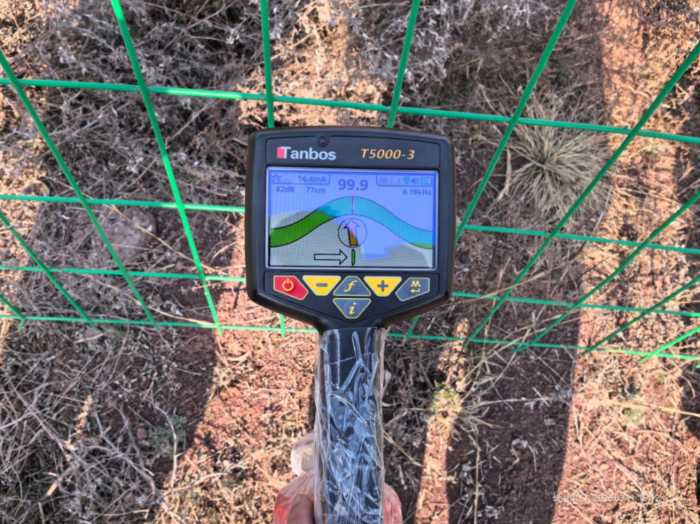
Equipment: Tanbos T5000-3 Intelligent Cable and Pipe Locator
At a solar PV site in Shanxi, the customer had incomplete records for a directly buried 35 kV three-core cable. With agricultural machinery scheduled to enter the area, accurately identifying the cable route was essential to prevent accidental damage.
The Tanbos engineer used the T5000-3 locator and a clamp-based signal injection method to apply an 8.19 kHz tracing signal without interrupting the cable's operation.
Key findings included:
-
The receiver's compass guidance enabled continuous route tracing without requiring a planned outage.
-
The measured burial depth was 77 cm, with a loop current of 56.4 mA.
-
The cable route was clearly identified, providing a reliable reference for marking the underground cable alignment.
-
The route marking was completed across the site within half a day, allowing the scheduled agricultural work to proceed.
The application helped the customer identify the buried cable before machinery entered the area, reducing the risk of accidental excavation damage.
Case 2: Verifying Cable Clearance Before Construction
Location: Jinzhong, Shanxi
Application: Cable route verification near a box-type substation
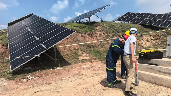
Two months later, another renewable energy site in Shanxi needed to determine whether planned construction near a box-type substation would overlap with an underground cable route.
The initial attempt was complicated by restricted access to the substation enclosure and unstable induced signals, preventing reliable route identification.
After the customer removed a metal panel beneath the enclosure to expose the cable, the engineer switched to the 8.19 kHz clamp-based tracing method. The cable route then became clearly identifiable.
The results confirmed that the planned construction area did not overlap with the underground cable route, allowing the potential risk to be addressed before work began.
Application value: Cable route tracing is not only useful for locating buried infrastructure. It can also support construction planning, help avoid unnecessary excavation and reduce the risk of unplanned outages.
3. Low-Resistance Insulation Fault: Pinpointing a Buried Cable Defect
Location: Changzhi, Shanxi
Cable: Approximately 1 km long
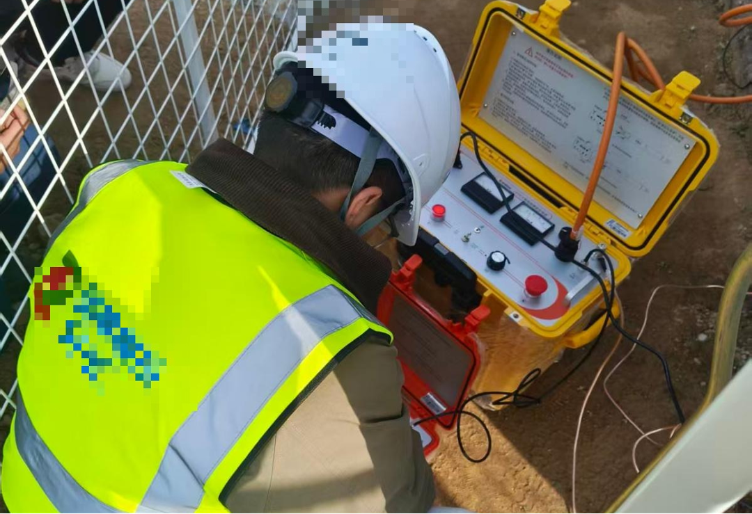
Equipment: Tanbos T8 Cable Fault Location System
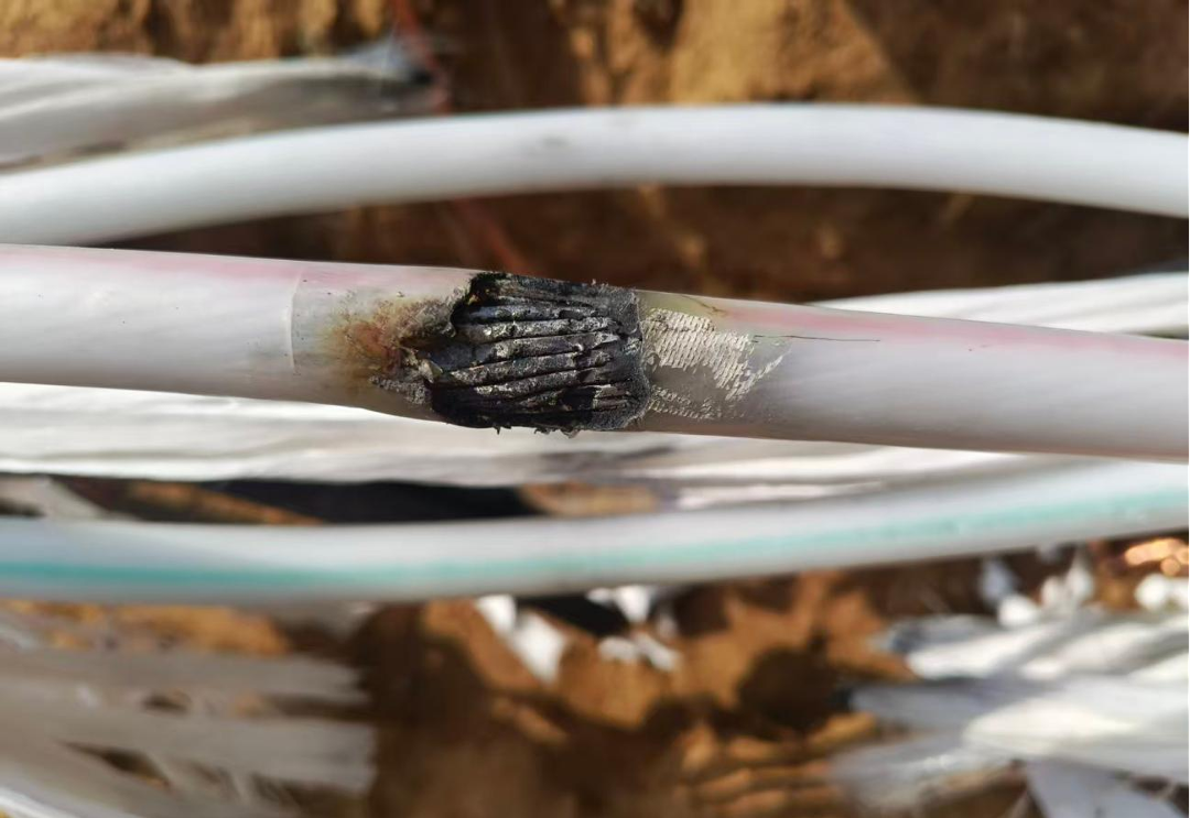
At a solar PV plant, insulation resistance testing identified a low-resistance fault on phase C of an underground cable. The measured insulation resistance was only 0.2 MΩ. A cable joint approximately 400 m along the route had already been opened, but the precise fault location remained unknown.
The Tanbos team applied a low-voltage pulse method using the T8 Cable Fault Location System to determine the cable length and estimate the distance to the fault.
The diagnostic process involved:
-
Measuring the cable length and pre-locating the fault at approximately 132 m.
-
Applying an impulse voltage of 7 kV to generate a discharge signal.
-
Using synchronized acoustic and magnetic detection to pinpoint the fault in the pre-located area.
-
Switching to adaptive noise reduction to improve signal recognition under strong mountain winds.
During excavation verification, the discharge sound was clearly detected through the headphones, enabling the engineer to identify the fault location in a single pinpointing attempt.
Application value: Combining electrical pre-location with acoustic and magnetic pinpointing can help narrow the excavation area and improve the efficiency of underground cable repair.
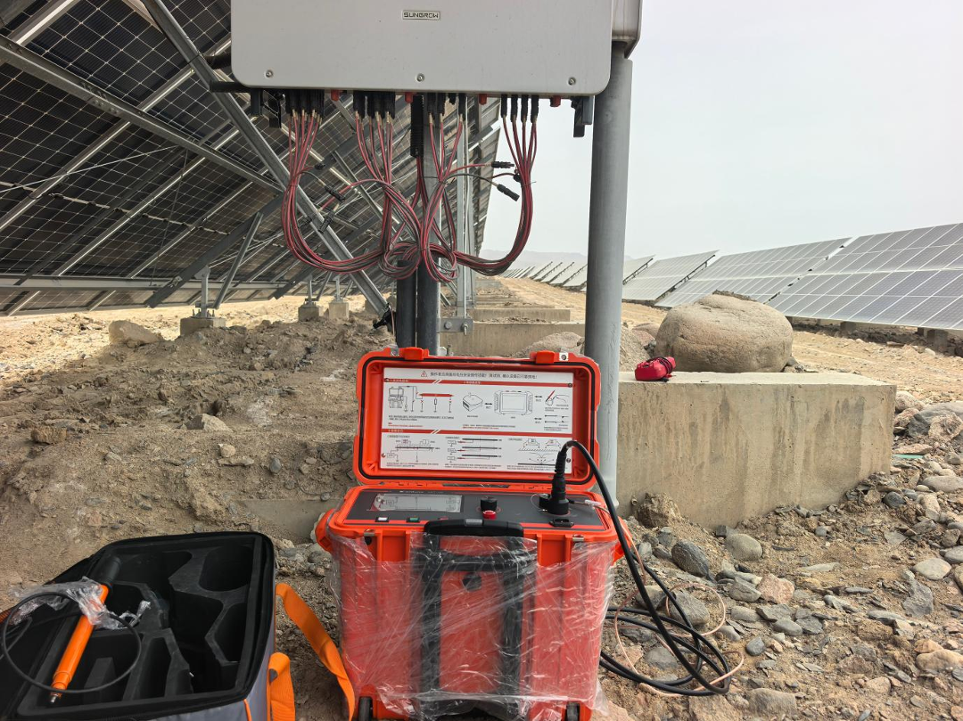
4. DC Ground Fault in a Solar PV String Cable
Location: Xinjiang
Cable: 750 V DC PV string cable
Equipment: Tanbos HC-10 PV String Cable Fault Locator and T5000-3
A solar PV plant in Xinjiang experienced a complete ground fault on the positive conductor of a 750 V DC cable. The cable was buried more than one meter underground, and its route was not documented.
Conventional surge-based methods were considered unsuitable for this cable construction because the cable lacked metallic armoring and had relatively thin insulation. Such conditions can complicate waveform acquisition and increase the risk of additional insulation breakdowns during testing.
The team used the HC-10 PV String Cable Fault Locator to diagnose the fault.
The procedure and findings were as follows:
-
A diagnostic voltage of 32 V was applied, and the measured insulation resistance was 1.07 kΩ, confirming a severe ground fault.
-
The T5000-3 was used to trace the cable route and measure its burial depth, which was approximately 1.06 m.
-
A step-voltage method was then used to pinpoint the fault along the identified route.
-
The fault was located approximately 2 m before the steel conduit on the inverter-side string.
The team also encountered challenges associated with Xinjiang's dry soil, which attenuated the step-voltage signal. Based on the site conditions, the engineers used controlled watering along the route to improve soil conductivity and strengthen the detectable signal.
Application value: This case highlights the importance of adapting fault-location methods to DC PV cable construction and local soil conditions rather than relying on a single testing technique.
5. Low-Voltage Cable Ground Faults in Different Installations
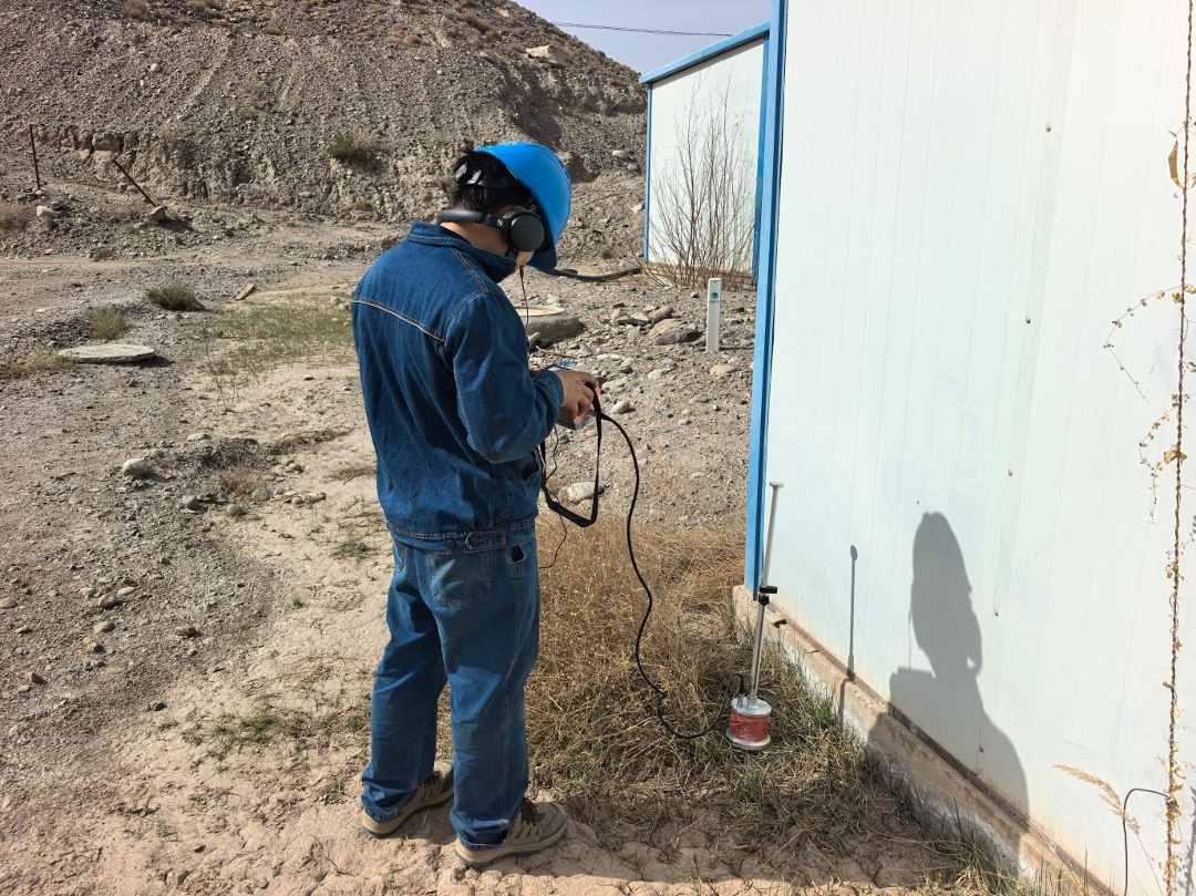
Case 1: Ground Fault on a Pump Motor Feeder
Location: Hydropower plant, Xinjiang
Cable: 400 V pump motor feeder
Equipment: Tanbos T20, LP30/2, WL20, T5000-3 and PP20
A pump motor feeder at a hydropower plant developed a single-phase ground fault. The cable route included sections installed in cable trays, cable trenches and direct-buried sections. Phase A showed insulation resistance in the kilohm range.
The Tanbos team combined several testing methods to determine the fault location:
-
The T20 Cable Fault Location System used low-voltage pulse testing to measure the cable's total length of 173 m.
-
The LP30/2 high-voltage surge generator and WL20 waveform reflection instrument were used to estimate the fault distance at approximately 160 m, near the pump room.
-
The T5000-3 traced and marked the cable route.
-
The PP20 acoustic pinpointing instrument detected a clear discharge sound near a cable entry opening in the pump room basement.
The fault was ultimately pinpointed near the outer edge of the pump room, helping limit the excavation area and minimize disruption to plant operations.
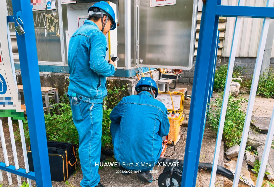
Case 2: Near-End Fault on a Low-Voltage Solar PV Cable
Location: Zhangzhou, Fujian
Cable: 0.6/1 kV low-voltage cable, 168 m long
Equipment: WL20, LP15/8 and PP20
At a solar PV site in Fujian, a 168 m low-voltage cable connected a box-type substation to a rooftop combiner box. The installation included directly buried, conduit-protected and cable-tray sections.
Insulation resistance on phases A and C was measured at only 0.02 MΩ, indicating a serious insulation fault with characteristics of a ground fault and short circuit.
The Tanbos engineers used the following procedure:
-
The WL20 was used to measure the cable length and analyze the reflected waveform. A compressed waveform period indicated a likely near-end fault.
-
The LP15/8 high-voltage pulse acquisition method was then used to estimate the fault distance at 23 m.
-
An 8 kV impulse was applied, and the PP20 was used for acoustic pinpointing.
-
A distinct discharge sound was detected approximately 20 m along the cable route, allowing the fault to be pinpointed successfully.
Application value: These two cases demonstrate how combining waveform analysis, cable route tracing and acoustic pinpointing can address low-voltage cable faults across different installation environments.
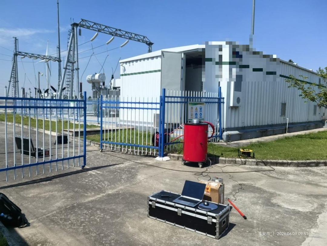
6. Oscillating Wave Partial Discharge Testing on a Wind Farm Cable
Location: Jiangsu
Cable: 35 kV three-core cable, 400 mm² cross-section, 154 m long
Application: Insulation condition assessment
Method: Oscillating wave partial discharge testing
A wind farm operator requested a comprehensive assessment of a 35 kV collection cable to help determine whether it remained suitable for continued operation.
The Tanbos team conducted an oscillating wave partial discharge test in accordance with DL/T 1576-2016, a Chinese industry standard for this testing method. The test voltage was increased in stages from 0.5 U₀ to 1.7 U₀.
The recorded results included:
-
Insulation resistance readings of at least 94.6 GΩ across all three phases.
-
A maximum recorded partial discharge level below 100 pC.
-
Discharge mapping showing a tree-like concentration of indications near the cable termination.
The recorded partial discharge level was well below the 5,000 pC limit referenced in the original test report. The overall test assessment indicated that the cable insulation was in good condition and met the criteria for continued operation under the assessment performed.
Application value: Oscillating wave partial discharge testing provides information about insulation condition and discharge activity, helping operators assess cable integrity and make more informed maintenance decisions.
Note: Acceptance criteria depend on the applicable standard, test procedure and equipment requirements. The numerical limits above are those reported for this specific project.
7. DC Cable Short Circuit: Investigating a 517 m Cable
Location: Xiamen, Fujian
Cable: ZRYJV22-1kV/2×95, 517 m long
Equipment: WL20 and LP15/8
In mid-July, a DC cable installation at an industrial site in Xiamen experienced damage at multiple points along a 517 m cable.
Initial multimeter measurements showed a resistance of 130 Ω on the positive conductor and 100 Ω on the negative conductor. The resistance between the conductors was approximately 0 Ω, indicating a metallic short circuit, with both conductors also showing ground faults.
The Tanbos team carried out the following tests:
-
Used the WL20 low-voltage pulse method to measure the cable length.
-
Applied the LP15/8 high-voltage surge method to capture current waveforms and estimate the fault distance at 89 m.
-
Conducted surge testing at 5 kV, limited by the available equipment settings, with a reported discharge energy of 100 J.
Pinpointing was complicated by densely arranged distribution cabinets and large warehouse equipment positioned above the cable route. During intermittent pinpointing, a discharge sound recurring approximately every five seconds was detected near a piece of equipment inside a covered structure. The signal characteristics were consistent with the suspected fault, but the equipment obstructed access to the exact location.
The next step was to coordinate with the site owner to relocate the obstructing equipment before completing precise fault pinpointing.
Although the final fault location had not yet been confirmed during this visit, the investigation produced several important technical observations:
-
Isolate the DC cable from switching equipment: Both cable ends must be disconnected from the switches before testing to reduce the risk of damaging switching equipment.
-
Apply appropriate waveform measurement configurations: The travelling-wave measurement method must be selected and connected correctly for the cable fault type. Connecting the conductor-to-ground in an unsuitable configuration can compromise the reflected signal.
-
Consider the fault discharge characteristics: A low-resistance metallic short circuit may produce little or no audible discharge. The test configuration and pinpointing method must account for the actual fault characteristics.
-
Clear physical obstructions before final pinpointing: When equipment or stored materials obstruct the cable route, access must be arranged before precise location work can be completed.
Application value: Not every fault investigation can be completed in a single visit. Reliable diagnosis also depends on correct test configuration, interpretation of field signals and coordination with site personnel.
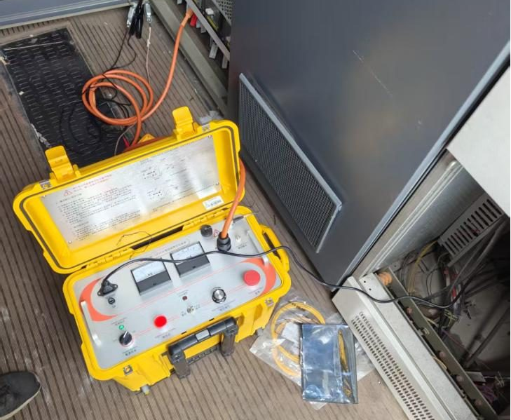
8. Equipment and Engineering Capabilities for Renewable Energy Applications
The nine site assignments demonstrate the value of combining specialized cable testing equipment with experienced field engineers. Different cable types and fault conditions require different methods, and selecting the appropriate combination is essential for reliable results.
Cable Route Tracing and Burial Depth Measurement
Tanbos T5000-3 Intelligent Cable and Pipe Locator
Designed for underground route tracing and burial depth measurement, the T5000-3 supported cable identification in construction planning and live-cable route tracing applications.
Cable Fault Pre-Location and Diagnosis
Tanbos T8 and T20 Cable Fault Location Systems
These systems support multiple diagnostic approaches, including low-voltage pulse testing, surge-based methods and synchronized acoustic and magnetic pinpointing, depending on the configuration and application requirements.
DC PV String Cable Fault Location
Tanbos HC-10 PV String Cable Fault Locator
The HC-10 was used to diagnose a ground fault on a 750 V DC PV string cable, supporting fault investigation in solar PV installations.
Fault Pinpointing and Waveform Analysis
PP20, WL20, LP15/8 and LP30/2
These instruments and associated equipment supported fault-distance estimation, waveform acquisition, surge generation and acoustic pinpointing across low-voltage and DC cable applications.
Insulation Condition Assessment
Oscillating Wave Partial Discharge Test System
The system was used to assess partial discharge activity on a 35 kV wind farm collection cable, providing test data to support the operator's insulation condition evaluation.
Equipment selection should always be based on cable construction, voltage level, fault characteristics, site conditions and applicable safety procedures.
9. Beyond Test Results: Practical Experience and Documentation
A complete field service deliverable involves more than identifying a suspected fault location. The diagnostic process also needs to provide traceable test records and actionable information for maintenance teams.
Across these projects, the Tanbos team prepared technical reports containing relevant waveform records, cable route information, test findings, conclusions and recommendations.
The field assignments also generated practical lessons for challenging conditions, including:
-
Using adaptive noise reduction when strong wind interferes with acoustic fault pinpointing.
-
Improving step-voltage signal detection in dry soil through appropriate field techniques.
-
Controlling signal current when tracing multiple cables installed in close proximity, in accordance with the applicable method and safety requirements.
-
Selecting suitable discharge configurations for low-resistance faults.
-
Considering the possibility of near-end faults even when the discharge sound is not detected at the nearest cable access point.
These observations complement instrument measurements and help engineers select appropriate testing procedures for future assignments.
10. Supporting Reliable Renewable Energy Operations
The nine sites served in 2026 were all associated with state-owned enterprise customers, whose operational requirements placed particular emphasis on safety, traceability and technical documentation.
For these customers, reliable cable diagnostics involved three key considerations:
Traceable and reviewable results
Recorded waveforms, route information and test reports provide a technical basis for reviewing findings and maintaining project records.
Safe testing procedures
Appropriate testing methods and equipment configurations help manage risks during live cable route tracing, fault diagnosis and insulation testing.
Experienced field engineering
Interpreting reflected waveforms, distinguishing fault signals from joint reflections and recognizing weak discharge signals under difficult site conditions require both technical knowledge and practical experience.
For renewable energy operators, these capabilities can support more targeted maintenance, reduce unnecessary excavation and help manage risks associated with underground cable infrastructure.
Conclusion
From solar PV plants in Shanxi and Xinjiang to hydropower facilities and wind farms in other regions, the 2026 field assignments demonstrate the range of cable diagnostic challenges encountered in renewable energy operations.
By combining cable route tracing, fault pre-location, acoustic pinpointing and partial discharge testing, Tanbos helped customers investigate cable faults, verify underground cable routes and assess insulation conditions across a variety of applications.
Cable diagnostics in the field requires more than specialized instruments. It also depends on selecting appropriate methods, understanding the limitations of test signals and adapting procedures to the actual installation environment.
Tanbos will continue to develop its cable testing technologies and field application expertise to support the safe and reliable operation of power infrastructure and renewable energy systems.