A company of Xianheng international
 EN
A company of Xianheng international
EN
EN
A company of Xianheng international
EN

Home > Support > Cases > Cable Fault Location
Case Study: Cable Fault Location on a 380V Cable
Ⅰ.Pre-Test Preparation
|
Test Date |
May 29, 2025 |
|
Test Location |
Shandong |
|
Laying Method |
Direct Burial |
|
Cable End Locations |
One end in the distribution room, the other in the distribution box |
|
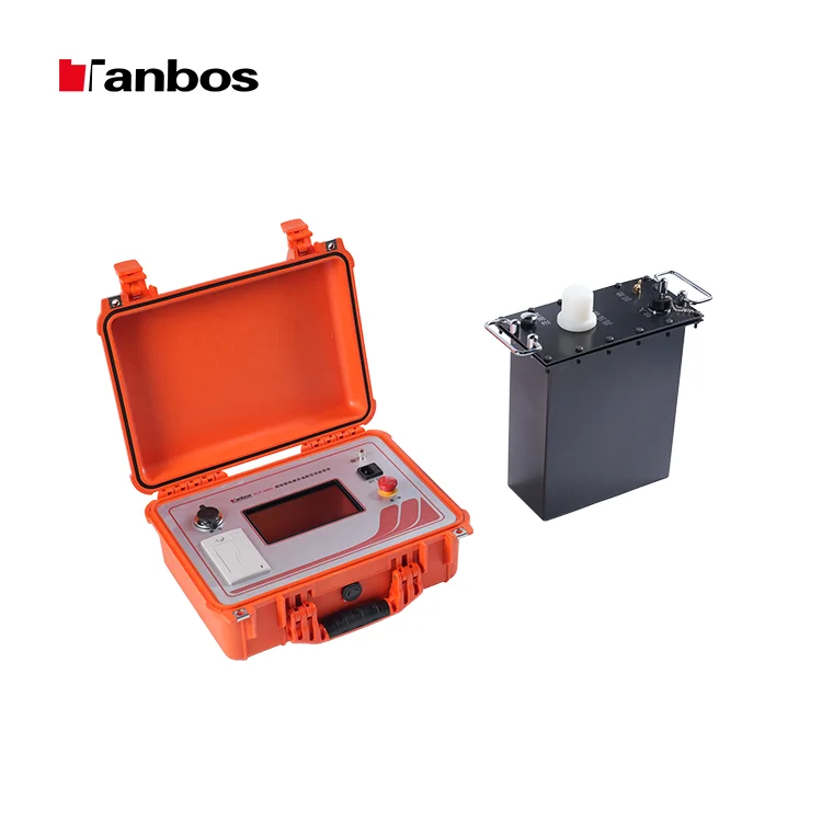
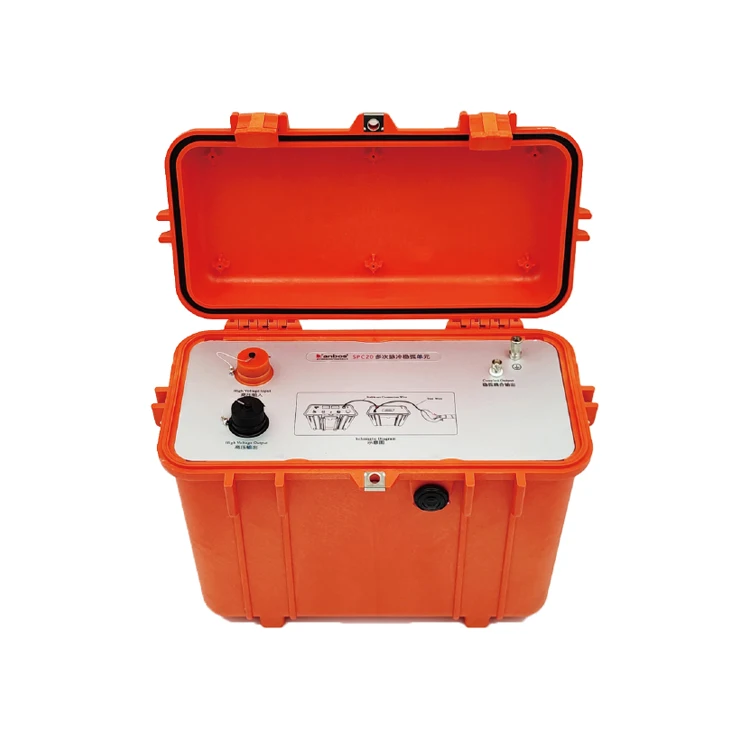
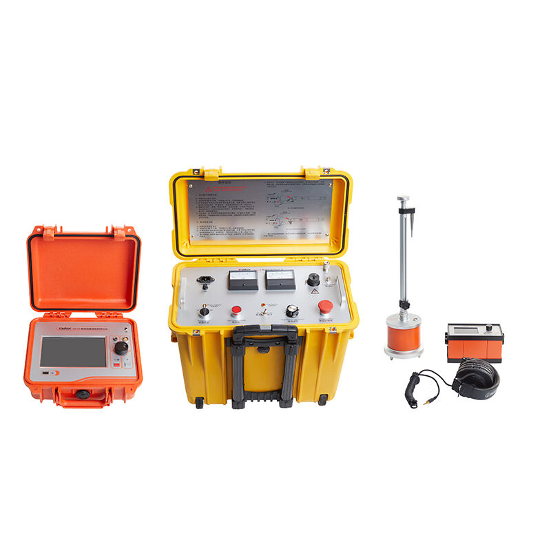
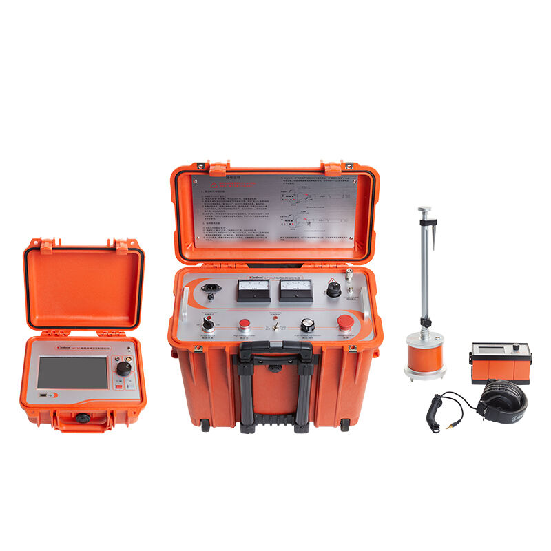
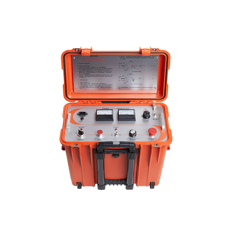
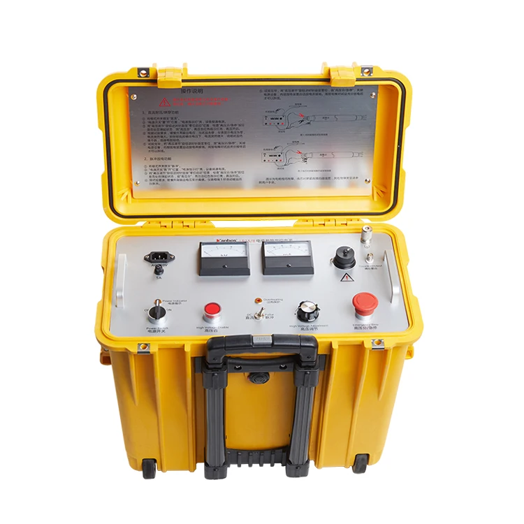
Instruments Used |
TBS-1000 Lightweight Intelligent New Cable Fault Locating Vehicle, LB4/60A Smart Bridge for Cable Fault Location, HC-10 Cable Sheath Fault Locating System, T5000-3 Cable and Pipe Locator |
|
Site Information |
A 380V four-core armored cable, over 100 meters long, was laid directly buried on a hardened road surface. Shortly after the power outage, a fault point was located two or three meters below the distribution box. After repairs, it was discovered that the cable still had a fault point. |
II. Testing Process
Step 1: Determining the Fault Nature
A 500V megohmmeter was used to test the three-phase insulation of the cable. The measured insulation to ground was: 50Ω for Phase A, infinite for Phase B, and infinite for Phase C. This indicated a low-resistance ground fault on Phase A. The Phase A showed continuity on the multimeter’s buzzer mode.
Step 2: Pre-locating the Fault
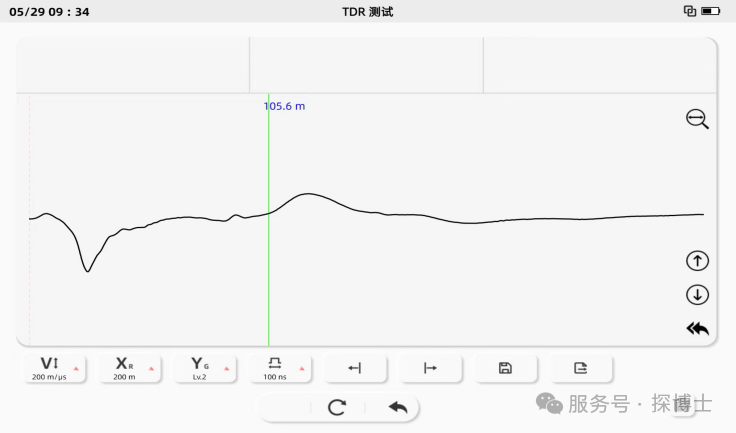
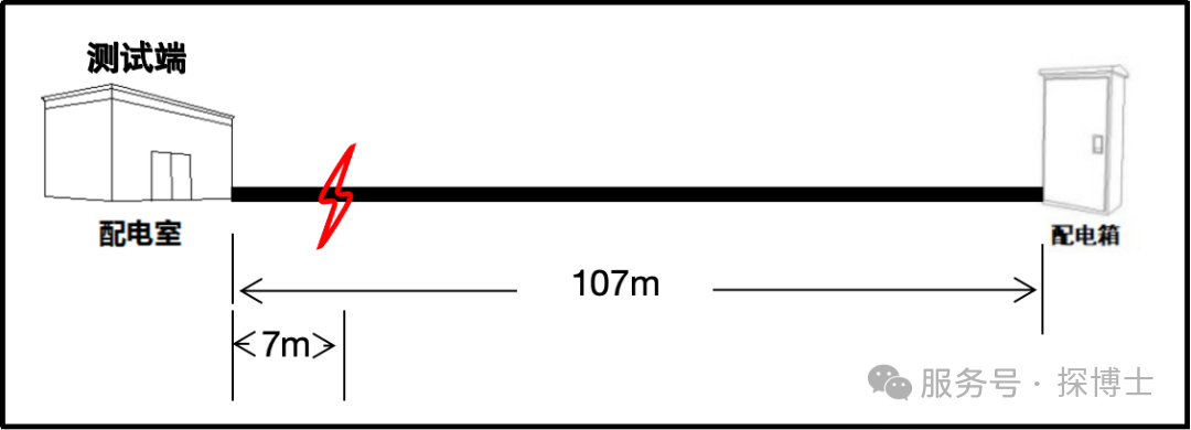
1.At the distribution room end, using the low-voltage pulse mode of the fault locator vehicle, the cable between Phases B and C was measured to determine a total length of 107 meters, as shown in the figure below.
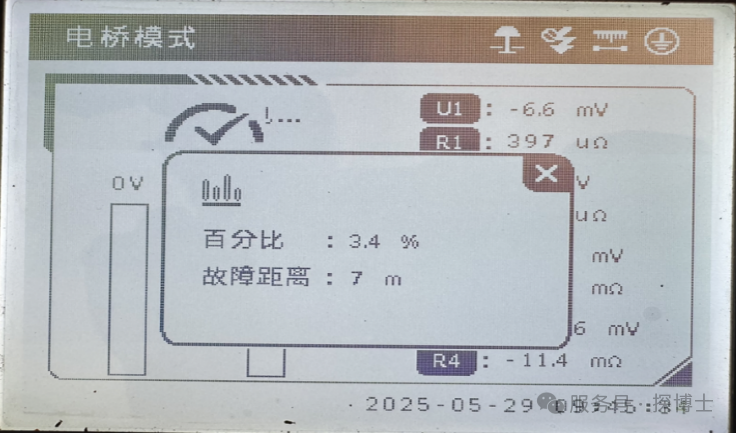
2. Because the cable armor at the distribution room end was not grounded, the traveling wave method could not be used between the fault phase and the armor. Testing the fault phase to ground also failed to produce an effective waveform. Therefore, the bridge method is used to directly test the cable fault distance. Setting different current settings, the bridge method measured the fault distance to be 6 or 7 meters at the near end. After changing the test end, the fault distance was measured to be 101 meters. The sum of the fault distances tested at both ends is consistent with the full length. As shown in the figure below:

Step 3: Cable Locator search The path is known and the path diagram is shown in Figure 4 below.
Step 4: Accurately Locate the Fault
1. Since the fault location, as determined by the bridge method, was 7 meters from the test terminal, a near-end fault was detected. To avoid interference from the equipment's noise from voltage application, the vehicle was driven to the terminal distribution box for pressurization and location determination.
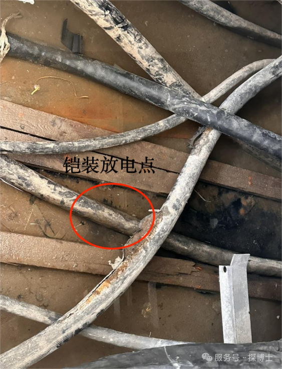
2. At the terminal distribution box, the customer had partially stripped the cable armor and grounded the armor. A 5kV pulse discharge was applied between the faulty phase and ground. A discharge sound was heard and sparks were seen in the near-end cable trench, as shown in Figure 5 below. After the high-voltage pulse was turned off, the cable was lifted, but no obvious damage was observed. Discharge from the armor was suspected. After the cable was suspended, pressurization was applied again at this location, but no discharge was observed.
3.Continue to pressurize the fault phase to locate the point. No discharge sound is heard at the fault point in the near-end cable trench. The cable comes down from the distribution room outlet cabinet and runs along the cable trench to the wall of the distribution room, and then is directly buried outside the distribution room. The length of this cable section is about 6 or 7 meters. No discharge sound is heard at the fault point at the direct burial position outside the wall, only a slight armor discharge sound.
4.Continuing to locate the fault point, we heard a discharge sound at a location approximately 75 meters from the test end, accompanied by ground vibration. This location showed signs of previous repairs, and upon inquiry, we learned that a water pipe had been laid previously, as shown in Figure 7 below. However, this location was significantly different from the distance measured by the bridge. We suspected that after the faulty phase was firmly connected to the armor, most of the energy from the impulse discharge was conducted through the wire core to the armor, causing discharge to the ground at the damaged outer sheath. The actual fault point was still about 6 or 7 meters closer.
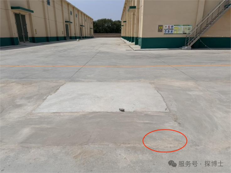
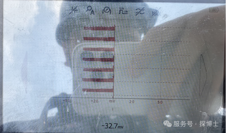
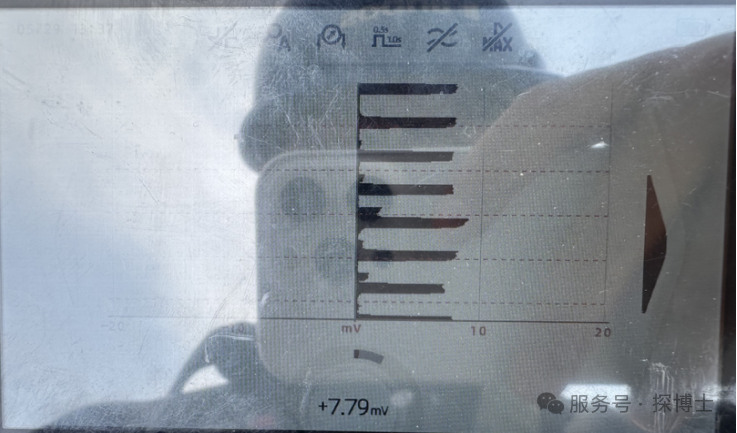
5.Since no discharge sound could be heard near the end, we planned to locate the fault using the step voltage method of the HC-10 outer sheath fault location system. The signal measured outside the distribution room wall pointed toward the far end and was approximately 4mV. This continued until 75 meters, where a noticeable discharge sound was detected, with a signal value of approximately 30mV. (Due to the concrete pavement at this location, testing was limited to a gap parallel to the cable.) Beyond this point, the signal direction shifted, indicating that the measured damage point was still located there. The signal changes are shown in the figure below. However, the results did not match those obtained with the bridge test, and the measured step voltage signal value was relatively low. We suspected that the fault point was not damaged externally, resulting in signal leakage from the point of damage on the outer sheath rather than the fault point.
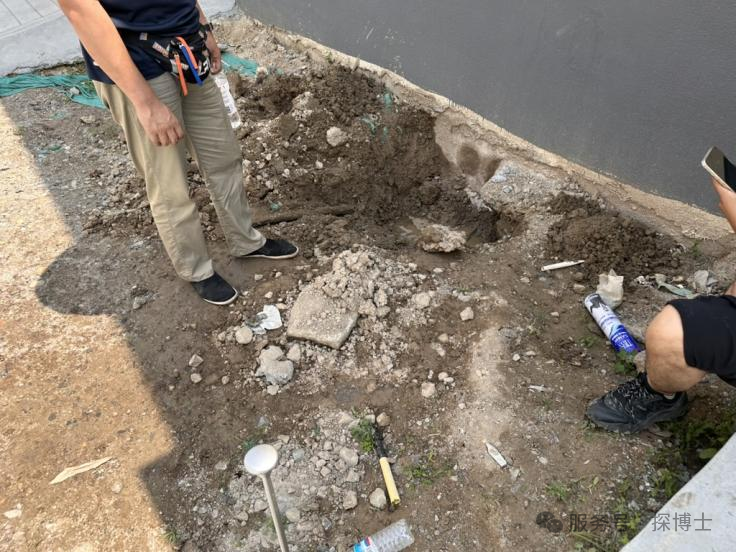
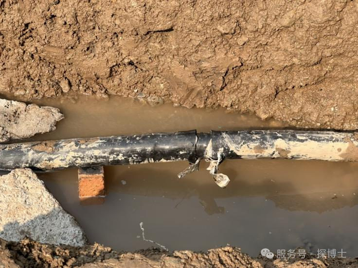
6.At this point, the cable was in trouble. The distance measured by the bridge didn't match the location of the damage point, as determined by the discharge sound and step voltage measurements. The cable was buried shallowly in a dirt road two or three meters after exiting the distribution room wall, while the discharge sound was heard on a hardened cement road surface, deeper. Therefore, they planned to excavate the dirt road first. After excavation, they observed no signs of damage or damage on the cable's outer surface. They suspected that the faulty phase was in a solid connection to armor with the cable armor. Therefore, they disconnected the cable armor at about eight or nine meters. Then, using a multimeter, they performed a continuity test between the faulty phase and the armor, as shown in the figure below. The test results showed that the cable core on the faulty phase was conductive to both ends of the armor, with a resistance of almost 0 ohms toward the test end and approximately 29 ohms toward the end. Re-pressurization confirmed that the cable was not discharging, and the discharge sound at the near-end armor had disappeared.
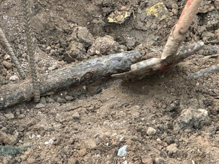
7.At this point, it was initially determined that the cable might have a multi-point grounding fault, resulting in inaccurate bridge test results. The discharge sound heard at about 75 meters was one of the fault points. Since the pressure was applied at the end, the discharge was preferentially from the first fault point near the end, and the armor discharge sound disappeared after the armor was disconnected at the near end. Therefore, the fault point at 75 meters was excavated first and repaired before testing. After excavation, it was found that the cable had obvious damage points, as shown in the figure below.
8. After the first fault point was dug out, plus the fault point previously found by the customer, there were already two fault points in the 107-meter-long cable. The cable had been laid for less than a year, so we planned to replace the cable directly without further searching.
III. Test Summary
01 Low-voltage cables are susceptible to multiple ground faults, significantly impacting the bridge test results. In this case, the traveling wave method or the step voltage method can be used for cross-verification.
02 When using the traveling wave method for fault location on low-voltage cables, do not test the core to ground. This is because the traveling wave signal from the ground is poorly transmitted, resulting in undetectable waveforms.
03 When using the step voltage method for fault location on directly buried hardened pavement, due to the special characteristics of the pavement, it is possible to test the pavement cracks parallel to the cable. Finally, the fault location can be determined based on the cable installation position. For hardened pavement, a steel chisel can also be inserted through the cracks to locate the fault.
04 Low-resistance dead-contact faults generally produce little or no discharge noise. However, the cable fault detection vehicle used in this case has a larger internal capacitor and a much greater discharge energy than conventional high-voltage generators, resulting in a noticeable discharge noise.
IV. Fault Cause Analysis
The fault point excavated was a small, nearly circular hole with bite marks around it. It was suspected that the cable insulation was damaged and punctured by insects and ants.
V. Operation and Maintenance Suggestions
1. Regularly inspect direct-buried cables to promptly identify and address potential safety hazards. Inspections should include the cable's appearance, insulation performance, and connector condition.
2. When laying cables directly buried, precautions should be taken to prevent soil corrosion, insect and rodent damage, groundwater infiltration, and mechanical damage.
 AR
AR HR
HR CS
CS NL
NL FR
FR DE
DE EL
EL HI
HI IT
IT JA
JA KO
KO NO
NO PL
PL PT
PT RO
RO RU
RU ES
ES SV
SV TL
TL IW
IW ID
ID SR
SR SK
SK UK
UK VI
VI ET
ET HU
HU TH
TH TR
TR FA
FA MS
MS GA
GA HY
HY AZ
AZ UR
UR BN
BN LA
LA MN
MN KK
KK